Proteus Industries liquid flow products
A Series of Articles designed to help customers in their liquid flow system applications using Proteus Industries liquid flow products.
Q: What are some general tips and guidance on fittings/connector selection and options when using my Proteus paddlewheel type flow sensor?
A: There are many considerations when selecting fittings for a Proteus paddlewheel type flow sensor. (Proteus also offers Vortex type flow sensors, which are covered in a separate note.)
In this discussion we find that such a seemingly simple issue can become very complicated indeed. The purpose here is to highlight the many nuanced considerations which the customer may then investigate further depending on their level of interest. Key subjects are:
- connection/fitting types: NPT, SAE
- connection form: elbows, straight pipes
- calibration: fitting’s affects
- assembly: each fitting type has unique assembly issues
- adapters: an easy way to size up or down, but beware of ID constraints
- Proteus custom fittings assembly and calibration services
Connection/fitting types:
From a bird’s eye view, Proteus Industries flow sensors range from 0.1~60 GPM flow ranges. The proportionally matching pipes and fitting sizes in this flow range are generally, ¼” through 1” sizes.
The most common fittings types are NPT and SAE with most common sizes available on Proteus flow sensors.
The most common NPT sizes in this range are: ¼”, ”, ½”, ¾”, 1”
The most common SAE sizes in this range are: 9/16-18, ¾-16, 1 1/16-12, 1 5/16-12
The advantages offered by NPT are: ubiquity, familiarity, performance (when properly assembled with Teflon tape).
The advantages of SAE are: position-ability (HUGE advantage, a must, with elbows), simplicity of assembly (error proof), excellence of integrated o-ring sealing (generally required for exotic thermal fluids), and with o-ring sealing no need for tape.
Connection form:
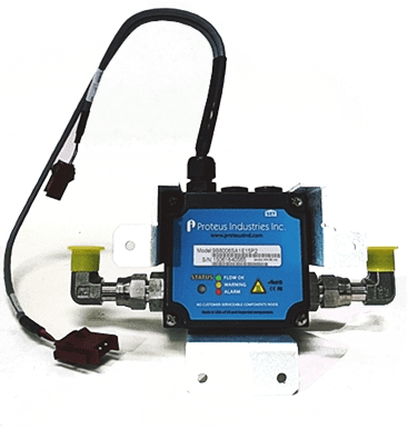
The 2 most common forms (shapes) of fittings with which to enter and exit the flow sensor are either straight pipe or elbow. It is generally recommended to use straight pipe whenever space allows. Straight pipes allow uniform flow profiles to develop and enter the meter, thus keeping factory calibrations valid. In the case of tight spaces, elbows may be required by users but then custom flow calibrations will be needed to account for the flow profile disturbances created by the elbow(s). Proteus Industries can assemble and custom-calibrate your sensor with the elbow fittings.
When using elbows into the Proteus flow sensor, we recommend that you do not use a standard NPT male, 90 degree elbow-type fitting because it is not designed for adjustable orientation. It should not be forced into the desired orientation. Using NPT elbows will always require the user to either over-tighten or under-tighten the connection to achieve the desired position. In other words, it would never occur that the fitting accidentally lines up perfectly in the user’s desired position while at the same time achieving perfect sealing force.
Calibration: fitting’s affects
Many Proteus flow sensors are pre-calibrated before they are shipped to customers. Proteus’ calibration process uses the recommended product data sheet direct to sensor attaching pipe sizes, i.e., a straight pipe with the proper run in + out lengths and of adequate inside diameter (meaning a diameter larger than the sensor’s internal diameter).
Consult the product Tech Ref Manual to find:
- the recommended minimum length of straight run inlet and outlet piping
- the recommended minimum ID of the inlet and outlet piping
If the customer then applies fittings of same or greater proportions and form (straight pipe), the factory standard calibration will remain valid. If, however, the customer applies fittings of smaller proportions (straight run in/out lengths and minimum ID), or different form (elbows) the calibrations will be invalidated to some degree. Again, Proteus can custom-calibrate the unit with customer specific fittings installed.
ASSEMBLY:
NPT: assembly of NPT fittings is an art unto itself. Many internet archives are available for reference, but the gist is that Teflon tape is required for a leak proof seal. The proper ‘feel’ is needed for the right seal requiring user experience. High quality parts should be used to ensure reliability and repeatability.
SAE: assembly of SAE fittings is simpler due to the “hard-stop” nature. Less ”touch” is required, one simply screws in until it stops (metal bumps into metal, the “hard stop”). The o-ring compression (the ‘feel’) is designed into the fitting already, so less expertise is required. The o-ring provides an excellent repeatable seal. And the BIG advantage: when using elbows, the fitting can be positioned into the exact stress free position that the user would like. This makes SAE mandatory when using elbows.
As a general assembly rule, whatever type connection is used:
- To avoid galvanic corrosion, keep like materials of construction together. Do not mix dissimilar materials like brass and stainless, or stainless and brass.
- To avoid mechanical compromise, do not mix plastic sensor flow bodies with metal fittings. CTE mismatch and over-tightening of the stronger metal fitting into the weaker plastic body will eventually crack the sensor body. This can be very insidious, not showing itself for years: the intitial installation will pass leak test, but over the years of thermal cycling and mechanical use, cracks will slowly develop and leaking will be noted for seemingly no reason. This is particularly true if the plastic flow body is injection molded plastic which tends to be both brittle and thin walled. If it is unavoidable that metal system pipe must go to plastic sensor body: use a transitional plastic ‘sacrificial’ adapter, and/or plastic pipe nipple, and/or plastic union to provide a potential service point for future and to avoid the dangerous metal into plastic sensor body situation.
Another general rule to keep in mind is that the greatest source of potential leaks from fittings is improper assembly. This truism points to the importance of assembly and leak testing procedures.
ADAPTERS:
Adapters make life easier. If you need to adapt up or down to suite a preexisting pipe size, you can use an adapter to save the day. If the sensor you want does not come in the pipe size you want, most likely an adapter exists which can help you to transition.
The potential pitfalls of adapters are:
- making sure the adapter selected doesn’t shrink the ID below the required spec if installed directly into the sensor’s inlet and/or outlet ports. If so, custom calibration would be needed, and again Proteus can accommodate.
- A good practice is to install the adapters a certain straight pipe length away from the sensor’s inlet/outlet ports. This would ameliorate any flow distortions created by the adapter. For example, use a 2~10” length of (appropriately sized length and ID) straight pipe nipple directly into the sensor which then terminates in the desired adapter. Try to adapt from larger (system) to smaller (sensor) whenever possible. If adapting from smaller (system) to larger (sensor), keep even greater distance of straight pipe run such as 12”~36”. This will allow the fluid to develop a uniform + correct flow profile. And again, Proteus can custom-assemble and calibrate your desired fittings to ensure your meter’s accuracy.
Proteus custom fittings assembly and calibration services
“Customization is our way of life!” Proteus Industries is happy to work with OEM’s to develop custom-assembled sensors + fittings AND custom-calibrate them together as an integrated unit. This will create greater meter accuracy and greater repeatability by eliminating multiple assembly steps.


